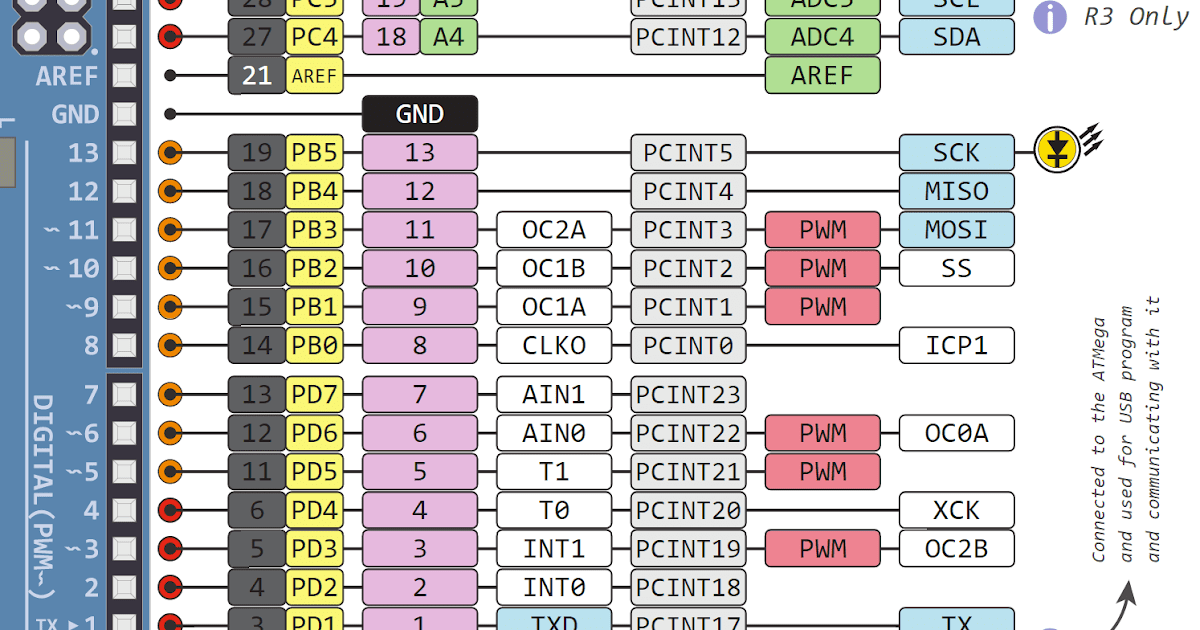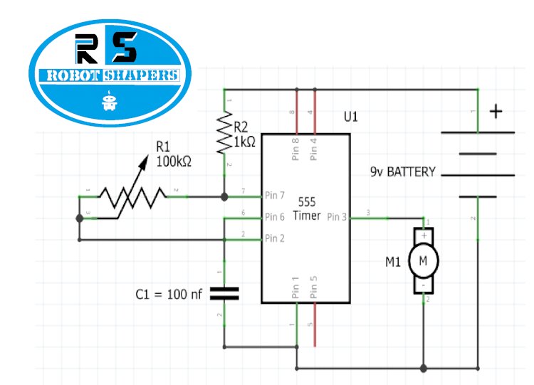

Problem Im running into with math is I cant generate 50hz with timer0 in FastPWM or PhaseCorrect PWM mode. Inside my loop, just for the purposes of testing, I'm blinking an LED just to monitor that millis is working. I have servo motor working with 2x555 timer cide to switch timers with attiny.
ARDUINO PWM TIMER FULL
This on-off pattern can simulate voltages in between the full Vcc of the board (e.g., 5 V on UNO, 3.3 V on a MKR board) and off (0 Volts) by changing the portion of. Digital control is used to create a square wave, a signal switched between on and off.

I am actually going to command a stepper motor using two square waves of 50 duty cycle on the two pins of PULSE and DIRECTION. Pulse Width Modulation, or PWM, is a technique for getting analog results with digital means. Set the two channels of a single timer to the same duty cycle, with one in non-inverting mode and the other one in inverting mode, and you have your complementary outputs. The PWM outputs can be set to either inverting or non-inverting mode. This tutorial focuses on the Arduino Diecimila and Duemilanove models, which use the ATmega168 or ATmega328.
ARDUINO PWM TIMER HOW TO
This tutorial explains simple PWM techniques, as well as how to use the PWM registers directly for more control over the duty cycle and frequency.

Im using an Arduino Uno to control it currently, but Id like to simplify my setup.

I also need to output 4 independant PWM signals. I am Alessandro and i am passionate about electronics so sometimes I run some mini projects as hobbist. I believe hardware PWM is the best solution to your problem. Introduction Pulse-width modulation (PWM) can be implemented on the Arduino in several ways. I have a question regarding sending a PWM signal to a brushless motor ESC using a 555 timer. Explanation of what I want to achieve : I use the IRremote library and need to produce a non continus 38kHz signal on pin 3, period is not important. So most likely I will want to implement a Phase Correct PWM Mode. Currently in my code, I configure the timers thusly: TCCR1A = (TCCR1A & 0b11110000) | 0b0001 Hi, Im having trouble using timer interrupt and using PWM at the same time. In this video, we discuss an important concept that is often misunderstood.We know that the Timer module is able to generate a PWM signal and at the same tim. I want to set Megas timer 5 pins 45 and 46 to 25kHz to change the speed of some PWM fans (25kHz so its not so noisy). The digitalWrite() function turns off PWM output if called on a timer pin. Learn how to use PWM (Pulse Width Modulation) output with Arduino.Īdd PWM output to your sketch using the analogWrite() function.I'm working on a project where I am wanting to use 4 PWM outputs, but I also use millis. Secrets of Arduino PWM is a great article that goes into much more detail.


 0 kommentar(er)
